欢迎光临~江苏美格地板有限公司
语言选择:
 ∷
∷

∷
 ∷
∷


Purpose:To determine the durability and/or deformation of access floor systems when exposed to commercially anticipated caster traffic using a specified load. Preparation:
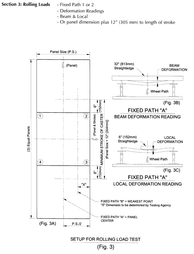
A restraining frame which laterally supports the mock-up assembly may be utilized to protect equipment or for personnel safety, provided said frame is constructed to not interfere with the panels or supporting understructure and provides clearance from any point of the mock-up prior to the start of test. Testing apparatus shall be designed to impose caster rolling loads directly on the mock-up system, with the load traversing in a fixed path on the three panels being tested. Dampening of mock-up, load, caster wheel applicator, load carriage or load bed is prohibited. |
 |
Test Procedures:
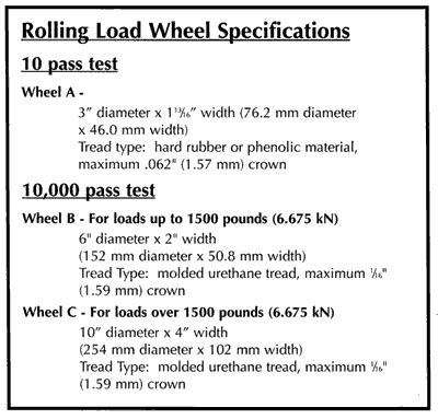
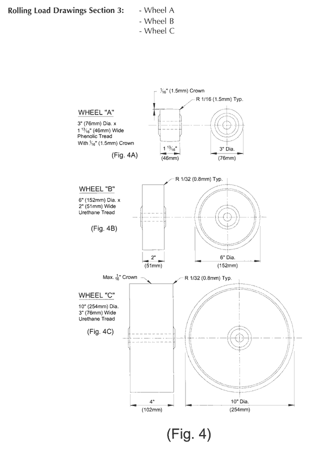
Path "1" Fixed path traversing across mock-up panels at panel centers. Path "2" Fixed path traversing across all three mock-up panels, along a line inboard and parallel from the outer edge as determined by the "weakest point." The "weakest point" is to be determined by the certifying independent testing agency and is defined as the path which yields the greatest top surface deformation under rolling loads as determined by this section. Wheel B and Wheel C shall be applied to separate mock-ups for each fixed paths 1 & 2 for 10,000 passes with deformation measurements at start and upon completion of 500, 5,000 and 10,000 passes. a. The center panel, prior to start of test, shall be measured for overall flatness utilizing a 32" (813 mm) long straightedge. The straightedge shall be placed parallel with each panel edge, flush with the edge or not more than 12" (12.7 mm) inboard from the edge. The straightedge shall also be placed along the diagonal in each direction. Measurement shall be taken at each straightedge location (6 locations) at the maximum variation and recorded and located for reference. (Note: If the panel configuration has an upward "crown", it shall be so measured and reported.) b. Prior to the start of test, the center panel, at points along the proposed caster path, shall be measures for local variation utilizing a 6" (152 mm) long straightedge. The largest six (6) variations shall be measured, recorded and located for reference.
a. The center panel, upon completion of test shall be measured in an identical manner as described in
b. Upon completion of test, the center panel shall be measured in an identical manner as described in
Report:
Panels: . Material(s) of panel construction. . Weight, nominal dimensions and thicknesses. Stringers and Pedestals: . Material(s) of construction.
. Weight, nominal dimensions and thicknesses, including fasteners, gaskets, coatings, Other: . Fully describe gasketing, pads, or other items utilized in the system. Wheel# (A, B or C) Imposed Load (lbs) (N) Fixed Path (1 or 2) Number of Passes *Deformation Reported (To nearest .001" [0,025 mm]) *Deformation reported shall be the maximum measurement for both beam deformation and local deformation.
|
 |
 |
联系人:陈先生
手机:+86-18861159966
电话:+86-18861159966
邮箱:info@maxgrid.com
地址: 江苏省常州市武进区遥观镇建农工业园